Technical notes regarding VSAT design: IFL cables, BUCs, LNBs and LO Frequencies
With an earth station or a VSAT terminal the electronic equipment like modems or routers will sit inside the building with the satellite antenna outside, sometimes on a roof or in a parking lot. The task of the satellite engineer is how to find the best way to connect the two parts together.
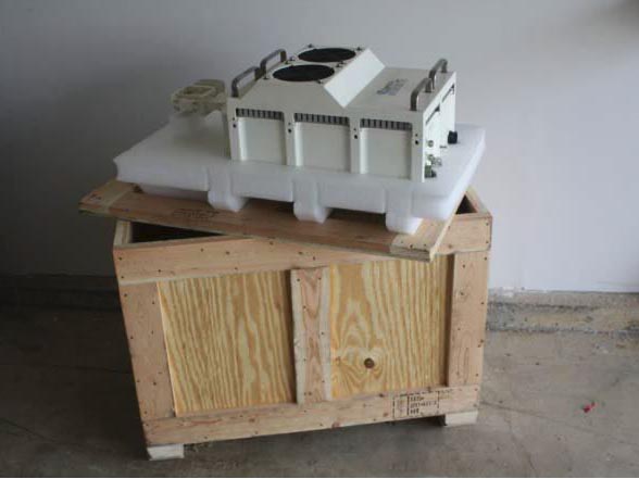
C-Band and KU-Band Transceiver
The problem with carrying high frequency signals over a long distance is that it is difficult and expensive. A 5 GHz signal cannot be carried over a simple cable, the signal loss per foot would be too great. To avoid this problem the engineers of the time devised a system to carry the signal over a much lower frequency than the radio frequencies required by the satellite. This lower frequency was named an Intermediate frequency (IF) and was typically in the 70 MHz region with the advantage that frequencies that low can by carried with little loss over simple cables.
The satellites operate at very high frequencies and so when the low frequency (IF) signal reached the antenna it had to be up converted to the satellite frequency by a transceiver and then transmitted via the antenna to the satellite. The transceiver had to be made reliable and weather proof and also had to perform the dual of 70 MHz to satellite frequency, and also the return signal of satellite frequency back to 70 MHz.
L-Band an Alternative to 70 MHz
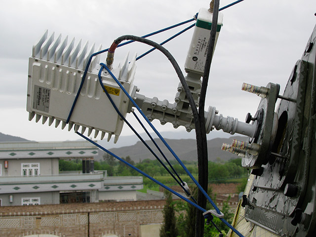
Beginning ten years ago a new amplifier called a BUC (Block Up Converter) began to be deployed because they were cheaper, lighter and often more reliable than the 70 MHz transceivers. The input to the BUC was via an L-Band intermediate frequency, and although higher than 70 MHz it was still possible to carry the signal one hundred meters using a cheap cable.
Types of Signal Cable
Connection from indoor equipment to outdoor equipment at the antenna, involves two inter-facility (IFL) cables. For L band, 75 ohm impedance cables with F connectors are common. For L band BUCs, 50 ohm cable is sometimes used and with 70 MHz systems 50 ohm cables are normal.
There is more dB attenuation loss on L band cables than with 70 MHz, particularly on very long lengths, but line amplifiers will compensate for the losses. Alternatively fiber optics can transmit either 70 MHz or L band and distances of several KM are possible.
Many BUCs and LNBs require power up to 48VDC delivered via the signal cable. This has implications for earth (ground) loops and corrosion, cables with very thin center conductors or high DC resistance with film screen/outers are not suitable. The best cables for any cross site application are foam filled Heliax, with solid copper outers, but cost rules this out for consumer installations. The more practical cable is LMR400 for the transmit portion and something similar to RG6 on the receive side.
Local Oscillator
A client recently asked why BUCs and LNBs use a Local Oscillator (LO) frequency. The Local Oscillator is what drives the mixer and allows the device to perform the frequency conversions. In other words an L-Band input will need to be converted to either KU-Band or C-Band and it is the LO frequency that determines the final output frequency. In the case of a Ku band BUC, the LO is normally 13.05 GHz so an L band input at 1 GHz comes out at 14.050 GHz. In the case of a C band BUC, LO frequencies of 4.9 and 7.375 GHz are used. In the case of 7.375 GHz the output is inverted so the modem modulation is set for inverted spectrum.
BUCs must have the LO frequencies stabilized by a 10MHz reference frequency that is overlaid on the signal and transmitted through the signal cable. This reference frequency must be accurate and with low phase noise. It is wise to check that the signal is clean and has not been contaminated by some local radio transmission.
A very long cable run can cause an erratic BUC current, when this happens consider putting the DC supply close to the BUC and use a Bias Tee to inject the voltage into the signal cable. There can also be problems for the LNB, as the return outer conductor drops varying voltages and these are superimposed on the LNB supply volts. The BUC and LNB are often partially connected to one another and to the earth ground at the antenna, so there is scope for strange voltages. Lightning and safety rules come first and the consequences of this may mean that you need an extra thick earth (ground) cable between the antenna and indoors equipment.
Note that 70 MHz transceivers can only transmit and receive over a small part of the satellite bandwidth, if it was required to transmit carriers 200 MHz apart it is necessary to use two up-converters. Alternatively you can get transceivers with 140 MHz center frequency for a much wider range of transmission frequencies.
If you get a transceiver make sure you understand how the frequencies are calculated. Sometimes a carrier at 70 MHz counts as zero frequency when added to the up-converter front panel readout setting, or sometimes 70 MHz.
Check first so that you don't transmit on the wrong frequency!
.jpg)